
Land Navigation
There have been questions on the forum about Land Navigation. Land Navigation (Land Nav) is also included on the MVT Rifleman Challenge. I am going to give you a run down of what you need to know, and some tips on practical application, below:
Maps:
General: a map is a birds eye view representation of the ground. It uses symbols, shapes, colors and contours to show what is on the ground. You should familiarize yourself with map markings so that you can read the map. Below is an Ordnance Survey (UK) map of the Brecon Beacons as an example. A map has various markings around the edge such as a key and scale, which will help you read the map. If you are looking for maps of your area, you should look at mytopo.com where you can get custom maps. If you are ordering maps you want them in either 1;50,000 or 1:25,000 scale. These are best for general military/navigation purposes. At MVT you will use a 1:25,000 scale map. You should order them in MGRS with visible grid lines. This will allow you to use grid references. Do not order them in lat/long.
![]()
HERE is a link to a page with some land nav presentations. There is one on basic map reading. Read them along with this post – there is almost too much information there, and I don’t want you to become confused. Use the presentations to get additional familiarity/practice.
Scale/Grid: a 1:25,000 map means one unit on the map (which size unit is irrelevant) equals 25:000 units on the ground. An MGRS map will have a series of grid lines on it. The eastings are the vertical lines and are numbered from left to right, along the bottom, top and at various points within the map. The northings are the horizontal lines and they are numbered from bottom to top, along the left, right and in the middle of the map as appropriate. You can see grid lines marked on the map above, eastings going from 97 through 00 to 05 (numbers are in the middle of the map because we can’t see the edges of this particular map excerpt, but it makes no difference. Imagine if your map was folded). The northings are numbered 18 thru 22, again you can see them in the middle of the map, in blue writing. These numbers are written on the blue grid lines.
Each grid square box is 1 kilometer, which is 1000 meters. On a 1:50,000 map the grid squares will just be smaller than on a 1:25,000 map, because everything is represented twice as large on a 1:25,000 map, which makes it better for detailed navigation.
Grid References: Now that we have these 1000 x 1000 meter boxes, it allows us to specify a point on the ground using grid references. We always read the eastings first, then the northings. You can remember this by “along the corridor, then up the stairs.” So we read the numbers that run left to right, then we read the numbers that run bottom to top. The graphic below shows this.
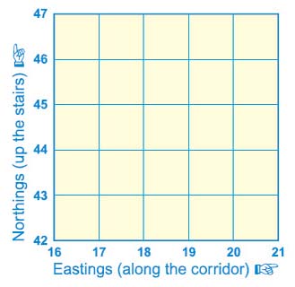
A ‘four figure’ grid reference simply gives us a 1 km square. Remember that a grid reference gives you the bottom left corner of any square, not the center. On the diagram above, the very bottom left corner of it has the four figure grid reference of 1642. That is 16 on the easting scale (along the corridor) and 42 on the northing scale (up the stairs). That gives us the bottom left corner of that 1 km box. The grid square at the top right of the diagram is referenced by 2046. 20 along the easting scale, 46 on the northing.
Look on the Brecon Beacons map above. You will find Pen-y-Fan center top of the map. Look at the blue grid line numbers. You will see that the 4 figure grid for Pen-y-Fan is 0121. 01 eastings, 21 northings. Note that this does not give the exact location of Pen-y-Fan, it just references the bottom left corner of the grid square within which Pen-y-Fan lies.
A ‘six figure’ grid reference gives us the lower left corner of a 100 meter box. The grid square is 1000 meter x 1000 meters. What we are doing is subdividing the sides of the grid square into 10 x 100 meter increments. This is not physically gridded, so you have to do it by eye or use a tool on your protractor/compass (more on that in a bit). In the diagram below, you can see our original 1 km square further divided into 100 x 100 meter boxes, with what is in reality an imaginary scale of 1-10 along the bottom (eastings) and side(northings). The 4 figure grid for this grid square represented is 1844.
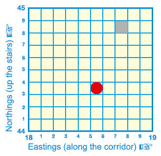
Looking at the diagram above, you can see the red circle. This highlights a 100 x 100 meter area. To give the 6 figure grid of this area, we first go along the corridor to 5 (eastings), then up the stairs to 3 (northings). This gives us the bottom left corner of the box highlighted in red.
The four figure grid was 1844.
The 6 figure grid is 18 5 44 3. Or 185443.
You have to figure out that it is a 6 figure grid and the first 3 numbers are eastings, the second three are nothings.
Without the aid of GPS, a 6 figure grid is really the best we can do. It gives you a 100 meter area.
In the diagram above, there is also a grey box. The 6 figure grid of the grey box is 187448.
An ‘8 figure’ grid reference gives you the bottom left corner of a 10 meter box. This means we further subdivide our 100 meter box into 10 further 10 meter sub-boxes. As shown in the diagram above, if we wanted to get more exact where within our red highlighted 6 figure grid box we were, we would sub divide it. Using compass/protractor analog skills, it is really nothing more than an estimate. We might say 1854 4436, written as 18544436. The initial 4 is an easting, saying 40 meters along the 100 meter box, the secodn 6 is a northing saying 60 meters up inside the box. If you are given an 8 figure grid during land nav, it allows you to dial in more specifically to where the check point may be.
Can we go to 10 figures? Of course, but there is no use for it in this application. That is a 1 meter location.
Looking back at the map of Brecon above , we can see that the 6 figure grid for the top of Pen-y-Fan is 012216 – it is in grid square 01 21. It is 2/10th (200 meters) east and 6/10th (600 meters) north of the bottom corner of that grid square.
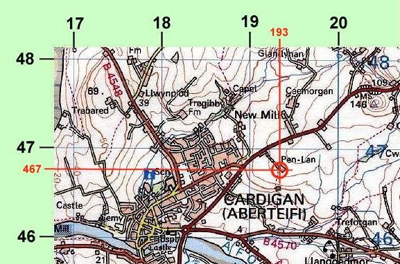
The map below shows a 6 figure grid 193467. Note in this case the eastings are read along the top of the map. It doesn’t matter.
Topography: other than symbols and colors representing various things on maps, such as roads, built up areas, woods and water courses, one of the main features on maps is terrain. A map is a 2D representation, and terrain relief is described using contour lines. Contour lines are usually brown. They are lines that join points of equal height above a reference height, usually sea level. You need to check out the key on a map to figure out what height separation each contour line is, and what unit of measure i.e. feet, meters etc. There is an index contour which is darker than the intermediate contours. Once important thing to remember is that there may be features between contour lines that do not quite break the height of the contour lines above and below, and therefore are not shown on your map – this could be anything such as small hillocks etc.
When looking at contours you have to imagine the contours and how the ground will look. The contours will define terrain shapes and also steepness – the closer the contours are together, the steeper the slope. There are a number of terrain features that you should be familiar with. Once you can use the contours to visualize the ground, you are on the way to being able to navigate using terrain association.
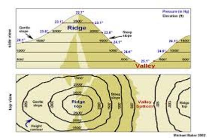
The graphic below shows how contours are used to build the shape of a terrain feature:
The diagram below uses numbered examples of the terrain features you should be able to recognize
The map below uses shading to bring out the terrain features – this is how you should imagine the terrain when you look at contours on a map:

Below: Hill:

Below: Ridge
Below: Spur
Below: Draw:
Below: Saddle
Below: Valley
Below: Spur (draw) Make a fist, your knuckles/fingers are the spurs, the gaps between your finger are the draws:
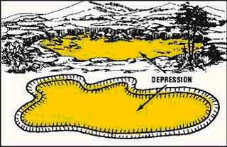
Below: Depression:
Below: Cliff (not shown by contours, but by hatching – contours would be too tight together):

With contours, a good tip is to use the water courses to help the terrain pop out at you. Streams will run down the low ground – in draws, not on spurs, so it helps to make sure you don’t invert the terrain in your mind. Also, where contours are marked with heights, the numbers will read so the top of the number is pointing towards the higher ground.
Grid Lines: An MGRS map is overlaid with a grid pattern. We already talked about this with grid references. The grid pattern is just used for the maps. The eastings run north-south and the northings run east -west. These are not the same as lines of latitude and longitude. In effect, it is a reference grid for taking grid references. This means that there are 3 norths as far as our maps go: True north, which is pointing to where the actual north pole is. Grid north is where the grid lines point to at the top of the map. Magnetic north is where our compass needle points to, which is not the north pole. Magnetic north also moves in increments as the magnetic pole shifts.
True north does not matter. The only ones that matter are grid north and magnetic north. Magnetic north only matters because we use a magnetic compass to navigate with.
Grid Magnetic Angle (GMA, or declination):
Because there is a difference in location of where our grid north is, and where magnetic north is, there is a problem with any kind of direction between the two. If I take direction on the map (also known as an azimuth, or bearing) and want to put it on my compass so I can walk it on the ground, the problem is that my compass points to a different north. Depending where you are in the world, the GMA varies. However, once you have worked it out, you know what it is. Think of it like an offset: if I take a grid bearing, I need to offset it to use with my compass. If I take a bearing with my compass, I have to offset it to use it and plot it on the map.
The GMA can be east or west of grid north depending where your map is. It is an angle off offset. The diagram below shows a GMA (also known as declination, or magnetic variation). You will find a similar diagram on your map:
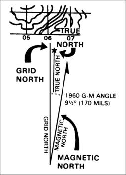
In this case, the magnetic error between grid north and magnetic north is east. This diagram has a 1960 GMA of 9.5 degrees. What this diagram would also need would be a rate of change – it would normally say, GMA 9.5 degres in 1960, changing by (for example) 0.5 degrees east every year. You would do the math and work out the current GMA! However, here the GMA (declination) is 9.5 degrees east. Now, with a basic standard of accuracy we can only really work in 5 degree increments with our compass and for practical navigation, so just round this to 10 degrees east.
What this means is that if I took a grid bearing from my map, and didn’t apply GMA to the compass bearing, I would be missing my destination by 10 degrees. You can have GMA of 30 degrees in some places, the more north you go! Be careful where you are in the world. However, once you know it for your area, you are set. In Romney it is currently 9 degrees west. So 10 degrees west for practical purposes.
So what do we do? Remember this: Error East, Compass Least. Error West, Compass Best.
So, with a west error as in Romney, the compass bearing will always be more than the grid bearing. It is 10 degress west, so if I take a bearing on my map of 270 degrees, in order to walk that with my compass, I have to add 10 degrees to make it 280 degrees. Think of it like: the compass is off to the west by 10 degrees, because it is pointing at magnetic north. In order to align it with the grid north, I have to add that 10 degrees. If the error is east, to align it I have to take the error off.
It’s like holdover with your rifle, or aiming off for wind.
If I am going from my compass to my map, with a west error I have to subtract it. Let’s say I took a compass bearing to an object and wanted to plot that on my map. If the compass said 320 degrees, then with a 10 west GMA I would subtract it going to my map, and plot 310 degrees on my map.
This isn’t much for short distances, but 1 degree is 1 meter at 1000 meters, so as you go further and with a larger declination (GMA), you will be off by more and more. You will miss the checkpoint. Unless you are also using terrain association!
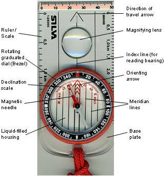
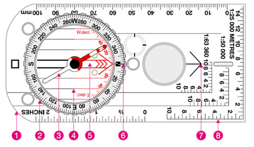
Compass: The military will have you use a lensatic compass. This is great for intersections, resections, fire missions, dead reckoning navigation etc. The problem is that there is no interface between your compass and your map. The interface is provided by a separate protractor. So for land navigation, patrolling etc, ditch the lensatic in favor of a Silva/Suunto style orienteering compass. Below: Silva Compass.

This type of compass will lay directly on the map and incorporates a compass and a protractor. It also incorporates (not all models do) a 1:25000 and 1:50,000 grid reference tool. You just slide it along the grid square and it tells you what the grid reference is.
On the diagram below, you see a Silva compass laid on a map in order to take a bearing. The long sides of the compass/the directionof travel arrow are/is laid along the desired direction of travel. You can see there are two black dots marked at the top side of the compass, and the desired direction of travel is between the two. You then rotate the bezel of the compass, which is marked as 360 degrees, so that the red internal arrow/north pointer is aligned with the grid lines (green arrow on the diagram). Make sure it is aligned pointing north on the map, not south, or you will walk opposite! It is at this point that you would take account of the GMA, in the case of Romney by adding 10 degrees, so rotate the bezel off by 10 degrees. Looking at the compass in the diagram, it looks like the desired direction is just south of east, or 106 degrees (green dot on the diagram). So add 10 degrees by rotating the bezel to 116 degrees.
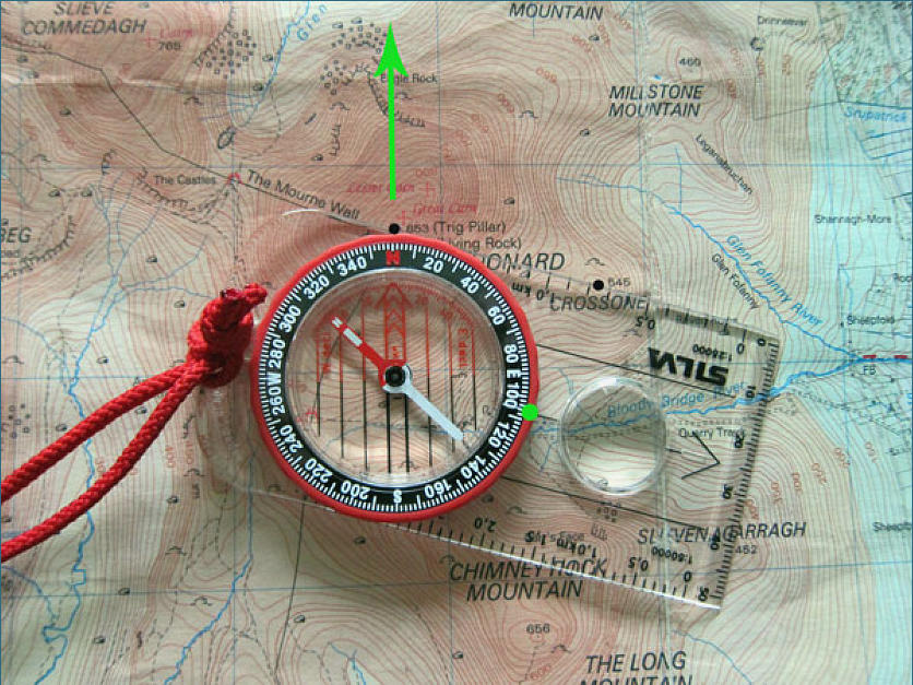
So now we have taken a bearing on the map, a direction we want to walk in, and made it into a magnetic bearing on our compass. Now, what you should be doing is keeping the map oriented to the ground. So that north on the map corresponds to north on the ground. This map orientation will then allow you to relate features depicted on the map, with features on the ground. So once I have taken my bearing, I can use both map and compass, or just compass. Holding one or both in front of me, I will turn around until the red needle in the compass lines up with the red arrow inside the bezel. I am holding the compass in my hand so that the direction of travel arrow points away from me. If I still have my map out, I can now orientate the map, if not done so already. Now, standing there with my compass held in front of me, I can look at the direction of travel arrow and then off into the distance where it points. I identify a point on the horizon and then I can start to walk towards it. Don’t walk staring down at your compass. Pick a series of points and walk towards them, picking another one every time one is needed.
Practical Navigation:
1) Ensure your checkpoint grid reference is accurately plotted on your map.
2) Know your departure point – orient the map to the ground and know where you are.
3) Make a route assessment of the best way to get between your points.
4) Use terrain association as much as possible: avoid azimuth/pacing type navigation as much as possible.
5) Use a green/amber/red system where you make your speed early (green), as you get closer you start to get into amber where you are navigating more carefully, then get to red as you are finally looking for the check point.
6) In conjunction with the above, use ‘attack points’ where you navigate as fast as possible using terrain association, then use a known point to attack the check point. This is where you may need to use a bearing along with pacing to find the specific location. An example would be using a known track junction to attack into thick woods for a couple hundred meters using a combination of bearing/pace count.
7) Know your pace count over 100 meters when running, walking and carrying your combat load. Go 100 meters then go back, taking an average. Count when your left foot strikes the ground. Carry a pace counter to record every 100 meters as you navigate on a leg. Don’t do all your navigation like this however, use terrain association where possible.
8) Handrail or use known features like ridgelines, trails or creeks. This is navigation, not patrolling, so where allowed use trails and linear features.
9) If heading across country, use terrain features and gradient to check off features. Example: crossed first creek, crossed first road, heading uphill, crossed ridgeline, heading downhill, hit second creek – in conjunction with a bearing and pacing this will keep you from getting lost. Also, use a backstop feature where you can i.e. I’m not crossing over the main ridge etc.
10) Aim Off: if heading for a checkpoint that lies on a linear feature, you won’t know which way to turn when you get to the linear feature, such as a road, to get to the checkpoint. In this case, deliberately aim off sufficiently to one side, hit the linear feature and turn in toward the checkpoint.
11) Contouring: this is where you stay at a certain height on the side of feature and simply follow the feature around. This is efficient because you gain/lose less height.
12) Cross -Graining: this is where you take an azimuth straight across country, over ridgelines etc. A direct route but not efficient. Lots of elevation gain/loss.
13) If you can’t find your checkpoint, don’t blunder on. Go back to a known location, such as the attack point, and try again.
If there are aspects that I have not included, or questions for clarification, I will take them in comments.
Thanks.
Max